It all started back in university. For my final year project, my advisor handed me a stack of complex formulas — each one pulled from a different design code, internally consistent but often contradictory.
The structure?
A steel hangar frame with a column of abruptly varying cross-section on one side and a beam with continuously varying cross-section on the other.
He said, “Solve this.”
I looked at the papers; he looked at me as if I was supposed to make sense of an unsolvable riddle.
That day, one thing became clear in my mind:
“I don’t just want to plug formulas — I want to truly understand what I’m solving.”
That was the beginning of a long personal and technical journey with lateral-torsional buckling (LTB).
From Empiricism to Analysis: A New Chapter with Eurocode
In the early years of my professional life, my engineering practice relied heavily on empirical formulas. They were fast, practical, and accepted. But that voice inside me kept asking:
“Is this really accurate? Do I actually understand why this works?”
Those questions eventually led me to Eurocode.
It wasn’t just a set of different equations — it was a structured, transparent, and physically grounded design philosophy. It offered not just results, but insight.
To implement Eurocode properly in our office, we acquired Dlubal RSTAB 8, a commercial software that, at the time, felt like a complete black box to us.
Initially, we used it like most people do: input values, get results. But as I dug deeper into the software, I realized something:
“This problem isn’t just about producing numbers — it’s about modeling and understanding behavior.”
And that was the moment I decided:
“I’m going to solve this my way.”
Defining My Own Path in MATLAB
Motivated by that decision, I began developing my own solution in MATLAB.
My goal wasn’t just to get an answer — it was to build the mechanics of LTB line by line, and understand each component along the way.
- I implemented a 7-degree-of-freedom beam element: axial, vertical, and lateral displacements; three rotations; and warping.
- I integrated a second-order (geometrically nonlinear) solver to capture equilibrium under deformed geometry.
- I introduced initial geometric imperfection using a sine function to simulate real-world irregularities.
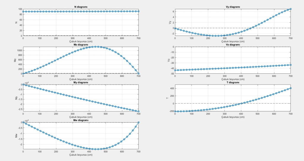
Then I validated the system using the Two-Hinged Frame example from Kindmann’s Steel Structures – Design Using FEM.
The MATLAB results matched the book perfectly.
When I modeled the same frame in RSTAB 8, the results were also very close, with the only difference stemming from the imperfection definition:
While I used a sine-shaped function, RSTAB automatically applies the first buckling mode.
What’s Next?
The next step is integrating automatic buckling mode extraction into the MATLAB code.
This will allow the imperfection to follow the actual first mode shape, reducing discrepancies and bringing my model even closer to commercial FEM software.
Conclusion
This journey wasn’t just about building a structural solver — it was about seeing engineering through a different lens, questioning the familiar, and trusting what I understood, not just what was given.
If you’re also seeking to truly understand how structural systems behave — not just solve them — sometimes it starts with a single question, and the courage to build your own answer.